Steve's Tiny Tugboat
Candu-EZ
Blog
So here I am on a new adventure. After
spending many years working on building a 4x4 out of a 1968 VW Bus, I am taking a
break.
My new project is to build a mini
tugboat. I have researched many different sets of plans out there. Each one has
its own mission. So -- what is my mission?
· I want a small tugboat that will easily move
4-5 people.
· Be able to get on plane and cruise around
35-40 MPH.
· While cruising below planning speeds, the
tugboat should look like the plans.
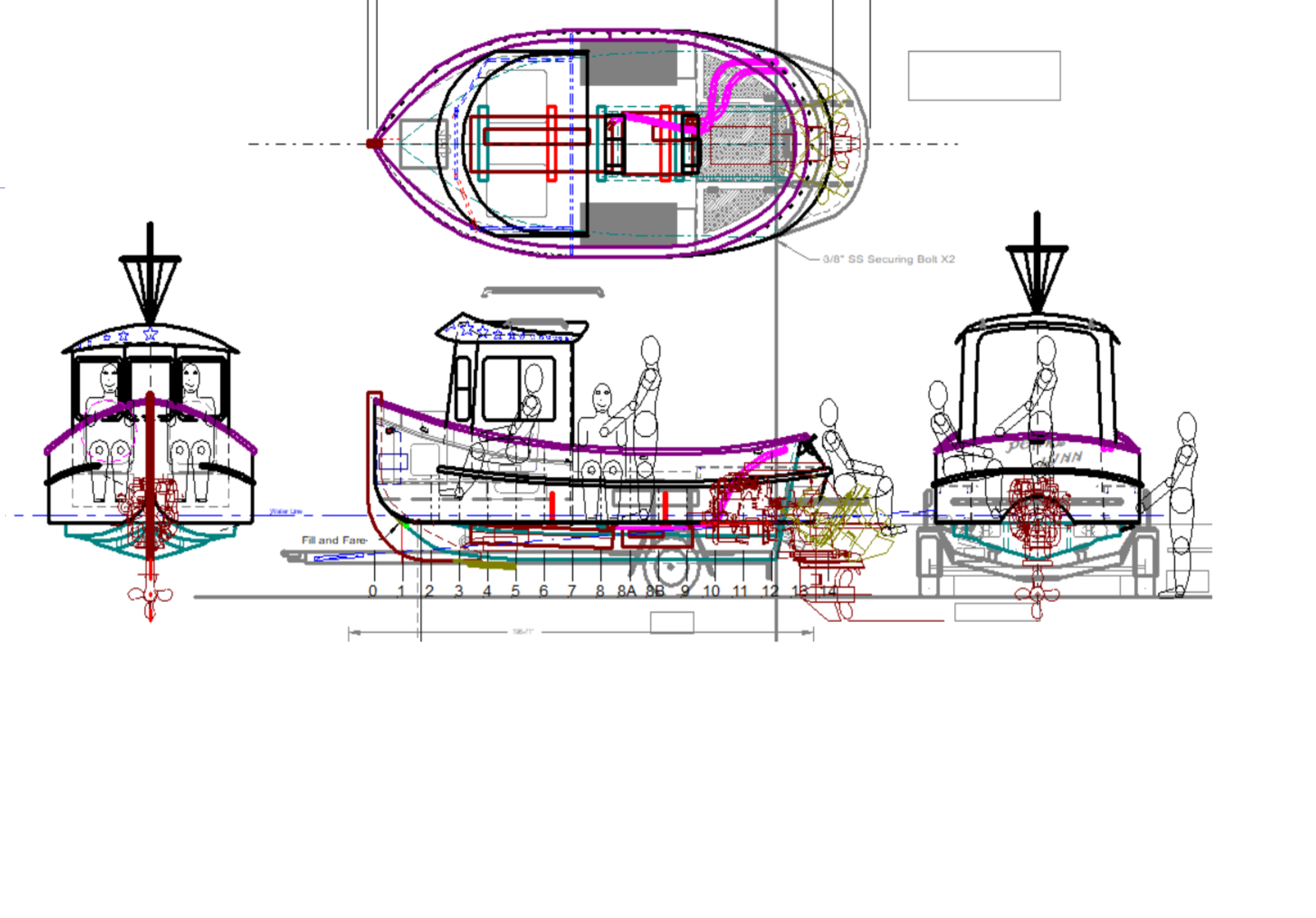
Which boat design did I pick, well I went with the Candu-EZ by Berkely.
I purchased the plans in September
2023. And started making the design changes:
- Increase the length by 2 feet (approved by the
designer at station “8”)
- V-Hull for planning
- Increased the height of the cabin by 4”
- Include an inboard/outboard (I/O)

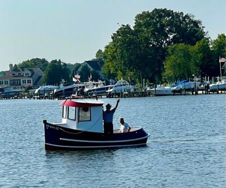
Here is an example of what it would look like on the water, but mine will be 2' longer.
As I do many nights, laying in bed
trying to fall asleep, an idea hit me: Find a fiberglass hull with no interior
for cheap. And walla – I found a 16’ Four Winns for $100 with trailer, motor,
sterndrive, trailer, and most important – PAPERWORK!
This is here is to document my
journey like I did with my 4x4 VW bus project.
October 2023
So this is what a 1987 Four Winns
Freedom looks like

Then it was time to strip it all down
Disconnect all of the wiring and
control cables
Disconnect the exhaust that goes to the stern drive
Transom now bare naked
Next was to remove the sides. If you have never cut fiberglass before, you just do not know the pure joy that you are missing in life. Fiberglass will absolutely destroy skill saw and Sawzall blades all day long. I do have a pneumatic 4” grinder. I bought some 4 ½” diamond blades and made a water cooler attachment to spray water on the blade while cutting. Worked FANTASTIC!!!
Sorry, no pics of the tool, but you get the idea.
Here is the hull with everything from the floor up removed. Kind of looks like a bass boat now.
Next was to remove the floor and see what lies underneath
Wow, what a mess!!!
Everything on the left side under the floor looks pretty good. The right side is another story.
Both main stringers are OK, but the secondary stringers on the right side will need to be removed and replaced with solid wood as well as the #1, #2, & #3 crossmembers all the way across
Next will be to remove the fuel tank. HMMM, I wonder if I could get another fuel tank ahead of the stock one for more gas. Time to measure.
I pulled the 16 gallon gas tank out.
By chance, I happened to find a 27 gallon gas tank for sale in my town for only $40. Ye-haw, upgrading from 16 to 27 gallons.
Side boards are bolted in place and sanded down perfectly level
These are 1x3 boards bonded with epoxy and bolted with galvanized bolts. These side pieces will provide the primary bonding surface for the floor to be attached -- as well as the stringers.
I will be adding some more at the inside edge of the bow.
Next I cut out the old rotted wood. Since this boat has the 3.0 4 cyliinder engine, the motor mount is located on the from of the engine, not the sides like you would see on V8 engines. All of the stringers are 1" thick. After removing the bad wood, I decided to bond 2x8 boards to the exisiting 1" thick stringers. This will add some strength to the rear of the boat as well as provide structure in the event I ever change out the 4 cyclinder engine to a V6 or V8. I have not installed the fiberglass yet.


I spent some time figuring out how I wanted to secure the 27 gallon fuel tank that I bought. Then it occured to me that I should use both tanks. Now for a 4 cylinder engine, 43 gallons of gas is an absurd amount of fuel. My reasoning is this:
- I already have the space under the floor
- I already have 2 gas tanks
- I don't have to fill them both up all the time
- I can choose to use either the front or rear tank depending of how the boat wants to ride
- If we do go on a long trip, I will not have to rely on dock fuel
- Gas in the second tank will act as a reserve tank
- And because I can :)
Cutting in the notches for the cross suports. The original cross supports were 1"x3". The new ones are 2"x4". The most rear support at the engine cut-out is a 2"x6". There will be 2 more supports added over the original layout. This will add a bit more weight, I know, but the floor will be very solid.
One more cross support to put in (need an acces hatch to access the sending unit for the forward tank).
Here you can see that I need to make some clearing for the fuel fill hose for the forward gas tank.
So I sanded, sanded, and sanded some more
Now that it is flat, I will lay down 2 layers of 6 oz fiberglass on the floor and about 3" up the stringers to ties it all back together.
Waiting for more epoxy resin and fiberglass to show up. Then it will be time to get some plywood and start the floor layout.
YEAH...Fiberglass supplies showed up. Layed down 2 layers of 6oz on the bottom and wrapped up about 3" on each side.
And now for some bad news...While getting the stringers ready for some fiberglass, I discovered a small hole at the starboard stringer transom junction. My finger poked right in there. I thought that the transom was solid...NOT!!! I thought about cutting out the bad wood and patch in some good wood, but upon further thought, it seemed that it would be easier and definately stronger to just replace it all.
I think that this ened up being a blessing in disquise. I noticed that the starboard side was never bonded to the plywood. It did make it 30 years like that, but it will be much stronger once the whole transom is bonded correctly.
All wood removed and sanded. There will be a little more clean up later.
Now I have the template made to cut out the new plywood.
1 Layer of 23/32 plywood which is full width. The outer edge shape is pretty close to what the angled hull sides will be. I will trim or extend as necessary once I start building the side walls from the floor to the gunwales.

Center section is 1-1/8" plywood. This will give a total thickness of 1-3/4" which will match the original wood thickness. The width of the original center piece of the transom was only as wide as the stringers. I decided to go a little bit wider to spread the load out. Also, the original center section was not bonded to the main transom plywood, it was only stapled (about 10-12 staples) and then about 2 layers of what looked like 6oz glass. This center section will be epoxy bonded to the main full width piece which will of course be epoxy bonded to the outer fiberglass shell. I will be laying down 2 layers of 1708 fiberglass over the center section then an addtional 2 layers of 1708 full width. This would be good for a V8 powered sterndrive. Since I am only running the Mercruiser 3.0, it will be really strong.
Plywood floor is layed down, not bonded yet. Plotted out the curve dots, and faired to a nice curve.
Cut the floor profile and cut several curve cuts so that I could radius up the tip. The 2x6s are there temporarily to hold the curve. Once the stem gets fiberglassed in place, the temporary supports can be removed.
Deviated from plans some more here:
Floor pattern was stretched 24" at section "8".
Plans do not call for the tip of the bow to curve up, the floor is completely flat on the plans.
Spent most of today working on the stem.
Deviation from the plans: Called for a 2x4 which would have been only 1.5" thick and 3.5" deep. I wanted something that was more substantial. I cut 2 pieces each 1-1/8" thick plywood which I will bond togther. This will give me a stem that is 2.25" thick and 6" deep.
Epoxy bonded the layers of plywood to the transom fiberglass outershell. I will let this stay clamped for 48 hours. Used pretty much every clamp that I have plus tightened the 6 sternrive bolts.
2 layers of 1708 fiberglass on the transom using polyester resin (probably the only thing that I will use the polyester for).
Also got the glass layed over the beefed up stringers.
Removed the stem, rolled on a layer of unthickened epoxy on each surface, and a decent layer of thickened epoxy to bond the 2 halves together.
Permanently installed the bow stem. 4 layers of 6oz each side on the outside. 3 layers each side on the inside. and started to bond the 27 gas tank in place.
Got the forward floor tip board installed and epoxied into place
3 Layers of 6oz fiberglass on each side on outside surface. Next will be to fill in the kerf cuts on the inside surface of the floor to make it smooth. Then lay down 3 layers of glass each side on the inside. The fabric that you are seeing is peel-ply. That will get peeled off after 2-3 days.
I filled all of the curf cuts with epoxy filler. Now that it is dry, time to sand 90% of it off.

Fiberglassed both sides
Applied the peel ply.
Ready to bond floor board #3 (Stations 7,8,8A,8B). Before I do that, I need to build a reinforcement trim piece around the access hole which allows access to the fuel sender, gas/vent line and filler hose to the forward 27 gallon gas tank. This will also be compliant with USCG regulations
This will get screwed and bonded to the underside of the floor and glassed in place.
3 layers over the access trim ring, and 1 layer over the whole floor bottom surface.
Peel-ply set down over the areas that will be bonded to the boat hull.
Filled in the gap between the fiberglass hull and the floor and layed down 3 layers of glass.
Later I will fare in the corners for the final shape, and add several layers of glass again.
OK, here we go, time to start installing the round stern. Sanded off the gel coat down to the raw fiberglass. set into place. There is a 2x2 ripped to match the stock transom to provide a level surface to bond the plywood down to (not shown).
Set nice and level
Max turn angle for the Mercruise Alpha drive is 35° -- Probably the max turn angle for any sterndrive to protect the u-joints.
Angles cut. I did install the sterndrive gimble to verify a good fit and proper turn angle clearances. But unfortuantely, I forgot to take a picture :(
It is now screwed and bonded to the stock transom.
The plans call to make a single template that will look like these (or close to it -- modified for this application). After the rear walls are installed, the template is to be removed. This is where I have made another change. I will have 2, and they will be premantently mounted -- now I have knees to help support the new round stern. I did this for a couple of reasons.
1 -- My round stern is seperate from the main floor
2 -- This tugboat will go significantly faster than the plans call for and one of the lakes here can get very rough. I wanted some additional structure to take the pounding.
The rear knees are bonded into place.
Installed 4x4 oak support. This will be what the rear tow hook will bolt too. There will be some addtional structure to tie this block to the forward structure, but that will be later.
Layed in some nice fillets. Once these cure up, I can start laying in the fiberglass to bond everything together.
Getting so close to flip the boat upside down. That might be a bit intense.
Installing the chine logs around the perimeter of the floor. This will provide the anchor point for the hull sides.
The flat area was a piece of cake, didn't take too long. When I got to the bow, this is where the fun began. The tip curves up and in creating a compound curve of sorts. It is really important that I create a vertical surface at the bow to hold the walls vetical when I install them.
I cut 3 blocks on each side. The top one has a 40° bevel cut on the outer edge. The middle blocks has a 20° bevel cut, and the lower is at 90°.
I then cut 1/2" plywood to match the upward curve ofthe floor, and had to bend it to match the inward curve to the stem
While match al of the curves, I was constantly using a level to make sure that the curve plywood was on a vertical plane.
In the end, I am happy with the end result. I will be adding some additional blocks on the inside to reinforce this mounting surface. This junction can NOT fail!!
Added 4 more gussett blocks to each side
Screwed and bonded the center bulkhead which will located the rear wall of the cabin. This will also give me a consistant square datum from the centerline going forward -- Finally!
Building a bracket for the back of the boat to lift it up. Its time to lift it off of the trailer and flip it to work on the bottom of the hull.
Rear lifting bracket in place.
1/2" bolts to attache the cable to.
Made a front bracket as well to bolt to the stem. I know its a bit rough, but it is temproary after all. Pleanty strong.
Engine hoist attached to the stem
Come-a-long attached to the stern
Lifted off of the trailer...jsut for the record, I was terrifed throughout this whole process!!!
Treialer almost out of there.
Starting the rolling process. The balance point was pretty nuetral.
Half way there.
Thinking of puttin a sign on the bottom of the boat: "if you are reading this -- call 911"
Starting to fare in the gap from the origianl fiberglass v-hull and the tugboat planform. Over 100 individual pieces of 1" plywood - each custom cut to fit.
WOW...an ton of work with little to show for it. Finally done cutting and fitting 220 individual plywood blocks. Once epoxy bonded inot place, there will be a lot of sanding to smooth out all of the edges. Then fare to the corner edge of the v-hull, then multiple layers of fiberglass to make one continuous shape.
Removed all of the 1" pieces (don't really have a name for them). Mixed some thicked epoxy and filleted the upper and lower corners.
Applied 2 layers of 6oz glass to secure the floor to the side attachment boards and the fiberglass v-hull.
Epoxy bonded the chine rail to the bottom of the floor.
Epoxy bonded 1/2" blocks next to the chine rail to the bottom of the floor. These were necessary so that when the 1" blocks are set into place, and the chine rail gets planed down, it will provide a smooth transition. You will see when we get there :)
Epoxy bonded all of the 1" boards in place
Filled any remaining gaps with thickened epoxy.
As we approch the end of February, I am making some good progress. Bonded all of the blocks in place. Also planed down the chine to be a reverse chine which will put the inside edge close to the blocks which will get a radius fill.
Pretty happy with the way the fillets are transitioning witht he strakes
Quite happy with the way the way this transition came out. Needed to add a Fore-Foot to fill the gap between the stem and the keel.
ITs really hard to try and find a picture that shows all of the curves. I am quite happy with how this side has turned out. This is the stem inot the fore-foot rto the keel.
Lets move to the stern for a bit. This shows the curved rear area of the boat. It will make more sense once the boat is flipped right side up. Normally the floor scetion would jsut be 1/2" plywood. However, since I am modifying and existing v-hull, this section is now cantilevered off of the v-hull transom. This structure is similar to a floating shelf: a box bonded to the fiberglass transom. This cavity will not be filled with foam. There rally isn't that much space in there anyways. I did completely seal the inside cavity. When completed, it will be waterproof from the inside and out, making this a sealed air pocket.
All epoxy bonded and screwed. Once cured, I will final sand the angles, router the edge and fiberglass to seal all of this up.
WHEW.....All bottom fiberglass is down. 3-4 layers Both sides.
2 layers rear curved decks
There was a valid question asked about how the the floor gets attached to the original fiberglass hull:
There are 2 blocks bonded and bolted to the FB hull. 2 layers of glass connecting the bottom of the floor to the side blocks and the FB hull. Built the new reverse chine onto the bottom of the floor. 3-4 layers of glass from the new reverse chine overlapping onto the FB hull reverse chine. Once the sides get installed, the glass from the walls will overlap the glass on the new reverse chine.
Here is a detailed drawing of the process.
After the epoxy had cured, I found a few air bubbles about the size of the tip of my pinky finger. Probably would have ben ok, but didn't like it. Ground those spots down to the wood (tapered bowl shape) and add fresh fiberglass.
Firt layer of epoxy filler. and sanded down. I think that just one more layer of filler and sanding and I will be ready to roll on the bottom primer.
There was just a small section that still needed to be faired. Small piece of foam bonded to the hull.
Foam sanded down to fit, and layed down the fiberglass. Once my new batch of epoxy and filler shows up, I can finish fairing the bottom.
Bottom of the keel was very chewed up. Not exactly sure how someone managed to get the entire length of the keel so messed up. There was also some gelcoat that was "globbed" on the bottom. Most likely someones attempt to repair damaged caused by some very rouogh beaching practices. I decided to sand everything smooth and fill all of the nicks with epoxy peanut butter.

Rolled on the bottom primer. I used Sea Hawk Tuff Stuff primer. It is a 2-part primer that provides an additional water-proofing layer. I have 1/2 gallon left that I will use up to the water-line once the sides are installed. This primer is THICK!!! I will use the Sea Hawk 2053 Thinner for the next run. This primer does seem to apper to provide a nice hard surface. Once the bottom paint arrives, I will sand the primer smooth then paint the bottom black. Once I can get the bottom painted, I will the FINALLY be able to flip the bottom hull right side up and start to build up the sides. Can't wait :)
You will notice that I did not apply the primer all the way to the edge. Once I apply the fiberglass to the walls, I will wrap the fiberglass around the lower edges onto the existing fiberglass on the bottom.

While I wait for the bottom paint to arrive, I decided that this would be a great time to tackle the trailer. If I am going to put so much time to make the boat look pretty, I want it to sit on a pretty trailer. Everything is getting stripped off. I have all new suspension on the way as well. Currently, this this trailer employs an odd slipper spring design. I don't like it. Besides, it appears that when the trailer was originally built, someone welded the rear slider bracket too far aft. With no weight on it, the edge of the spring "hook" is at the horizontal pin. As weight is placed on the trailer springs, the location gets worse. It apparantly has worked all these years, but I just don't like it. Besides, these springs are rusty and the trailer sits VERY low which leads tot he aft end of the trailer to scrape on the slightest in incline changes.

These rollers on the back of the trailer will be cut off and relocated to the aft fender "step". I am doing this since the widest part of the boat is no longer at the transom location. The widest section is now about the mid-point of the boat.
Change of plans, I am leaving the aft rollers off for now. If I feel that I need them later, I can always add them later. All sanded down to bare metal and 1 coat of Rustoleum Rusty Metal Primer.


.jpg)


